dkemm
Well-known member
Every time I take on a new project on my LR Ninety....I tell myself that I am going to document it - pictures, timelapse, video....
So far, I have installed my Cummins R2.8, swapped LT77 FOR R380, Marsland Chassis swap, interior leatherwork, fusebox upgrade, etc.....
Well, at least this time I took (some) pictures to document the work.
I will preface this post - explaining that I am not a trained mechanic or fabricator...just passionate about learning and creating! I dont have a fancy shop or magical tools - the work is done in my carport - so I am limited by light, weather and space.
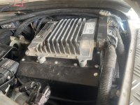
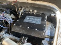
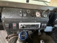
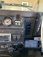
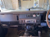
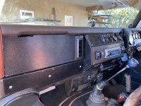
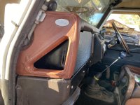
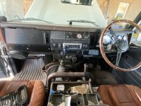
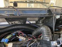
I live in the desert SW - New Mexico...typically we have what I would consider mild weather -- a few days a year over 100, some snow, a few days a year under 10degrees. For this reason, AC was not a must have item for my rover...the power windows were my form of AC. This summer we had a couple of weeks above 100 and I realized that I had enough "character building" in my life. I stumbled across MoD's offering and was intrigued by the fact that I didnt need to give up knee room inside my cab as the unit replaced the stock heater box. As it was - I had removed the heater box earlier in the year when I did the Chassis swap as I had already installed a webasto (knockoff) diesel heater for the cab space. In reviewing the MoD site, forums and watching their videos - I considered going the route of doing a full PUMA dash upgrade....but ultimately decided against that.
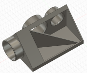
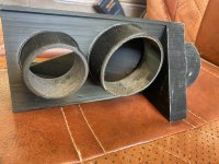
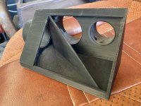
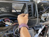
I placed my order and received my package in less than 2 weeks. I was pretty excited to open the box and see what I got myself into. The packing and organization of the MoD unit was great. I opted not to get a compressor from them to save on the shipping - and as I would need a bracket as well for my R2.8...I ordered those from Quick Draw Brand - arrrived in about a week. Now I had boxes of "stuff" and I had to come up with a game plan. Where to start, do I work in pieces so that I could still daily drive it, what needed to be done first..... as noted....I had previously installed a cummins R2.8 so I would be doing some customer fab work and positioning of items....
The Game Plan:
#1.
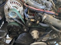
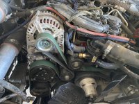
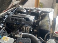
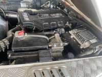
I decided to start by installing the Compressor and Compressor bracket on the R2.8. The new bracket had the power steering pump moving a little lower, so I did have to take into account the high/low pressure lines (braided SS lines). As I had a small leak from one of my fittings...I decided to simply create a new (slightly longer) hose with new fittings. Pump relocated, new lines in (no more leaking!!!) and new serpentine belt installed... a couple hours of work in the late afternoon.
#2.
Next up...redesign of my R2.8 cooling package. A little back story....as this will be somewhere in the v3.0 realm of R2.8 cooling.... The R2.8 dont like to be HOT....as they will throw codes and 'limp along'.
My v1.0 cooling was a single pass radiator - about factory size - a similar sized intercooler (cosworth RS500) and a 'standard' electric fan. This worked most of the time....
My v1.5 cooling was to add a bigger (more CFM) electric fan and reduce the size of the intercooler to provide clean air to the radiator - all this helped a little bit - but still got HOT
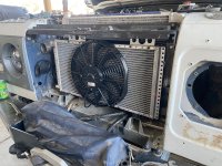
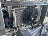
My v2.0 cooling was to add a 35% larger - Dual pass radiator (fills up the front space) and to move to a mechanical 17" fan - this solved all the H2O heat issues
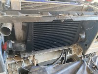
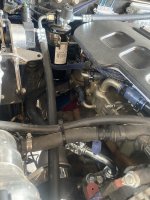
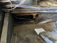
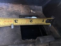
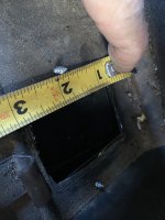
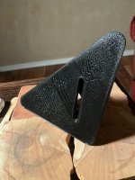
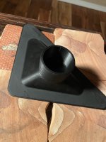
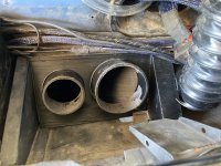
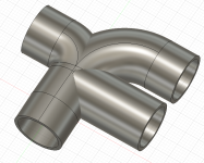
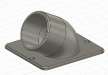
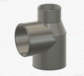
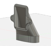
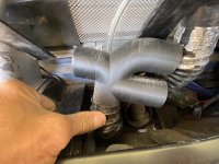
My new v3.0 cooling - I had to accommodate the MoD condesor/fan and wanted to upgrade the intercooler - middle ground between the Huge and small to provide for better turbo air cooling. This required some cutting into the inner fender well (not too concerned as I was already far from stock...and not a NAS) to fit the FMIC pipes...but allowed for a more direct cool air exit / out of the radiator path (previous FMIC design).
So far, I have installed my Cummins R2.8, swapped LT77 FOR R380, Marsland Chassis swap, interior leatherwork, fusebox upgrade, etc.....
Well, at least this time I took (some) pictures to document the work.
I will preface this post - explaining that I am not a trained mechanic or fabricator...just passionate about learning and creating! I dont have a fancy shop or magical tools - the work is done in my carport - so I am limited by light, weather and space.
I live in the desert SW - New Mexico...typically we have what I would consider mild weather -- a few days a year over 100, some snow, a few days a year under 10degrees. For this reason, AC was not a must have item for my rover...the power windows were my form of AC. This summer we had a couple of weeks above 100 and I realized that I had enough "character building" in my life. I stumbled across MoD's offering and was intrigued by the fact that I didnt need to give up knee room inside my cab as the unit replaced the stock heater box. As it was - I had removed the heater box earlier in the year when I did the Chassis swap as I had already installed a webasto (knockoff) diesel heater for the cab space. In reviewing the MoD site, forums and watching their videos - I considered going the route of doing a full PUMA dash upgrade....but ultimately decided against that.
I placed my order and received my package in less than 2 weeks. I was pretty excited to open the box and see what I got myself into. The packing and organization of the MoD unit was great. I opted not to get a compressor from them to save on the shipping - and as I would need a bracket as well for my R2.8...I ordered those from Quick Draw Brand - arrrived in about a week. Now I had boxes of "stuff" and I had to come up with a game plan. Where to start, do I work in pieces so that I could still daily drive it, what needed to be done first..... as noted....I had previously installed a cummins R2.8 so I would be doing some customer fab work and positioning of items....
The Game Plan:
#1.
I decided to start by installing the Compressor and Compressor bracket on the R2.8. The new bracket had the power steering pump moving a little lower, so I did have to take into account the high/low pressure lines (braided SS lines). As I had a small leak from one of my fittings...I decided to simply create a new (slightly longer) hose with new fittings. Pump relocated, new lines in (no more leaking!!!) and new serpentine belt installed... a couple hours of work in the late afternoon.
#2.
Next up...redesign of my R2.8 cooling package. A little back story....as this will be somewhere in the v3.0 realm of R2.8 cooling.... The R2.8 dont like to be HOT....as they will throw codes and 'limp along'.
My v1.0 cooling was a single pass radiator - about factory size - a similar sized intercooler (cosworth RS500) and a 'standard' electric fan. This worked most of the time....
My v1.5 cooling was to add a bigger (more CFM) electric fan and reduce the size of the intercooler to provide clean air to the radiator - all this helped a little bit - but still got HOT
My v2.0 cooling was to add a 35% larger - Dual pass radiator (fills up the front space) and to move to a mechanical 17" fan - this solved all the H2O heat issues
My new v3.0 cooling - I had to accommodate the MoD condesor/fan and wanted to upgrade the intercooler - middle ground between the Huge and small to provide for better turbo air cooling. This required some cutting into the inner fender well (not too concerned as I was already far from stock...and not a NAS) to fit the FMIC pipes...but allowed for a more direct cool air exit / out of the radiator path (previous FMIC design).