Building the perfect 90

erover82

Well-known member
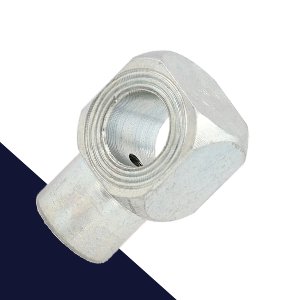
Several LR engines over the years featured baffles prior to the positive crankcase ventilation port to prevent excess oil flowing through the separator. Tdi engines however did not, so I made one.

IMG_5036.jpeg
IMG_5037.jpeg
IMG_5038.jpeg


Used rubber gasket dressing on all rubber gaskets including the valve cover to give the best chance at a long leak-free life.
IMG_5039.jpeg


Remember this?
66866586621__0C1A733F-A086-44FB-BA3C-30661F0E95F6.jpeg

This was aggravating, to say the least. The new shaft was not properly engaged and so resulted in one oil pump mounting ear shearing off as it was tightened. I immediately shuddered at the thought of what a new genuine oil pump might cost from such a stupid mistake, and how many more weeks I'd have to wait for it, yet again.

Well the new oil pump arrived, mounted up fine, and I was able to move on.
IMG_5030.jpeg


Moving on to the front side, I installed the timing belt with all new OEM components and set the valve/fuel timing. If you look closely you'll see yet another threaded insert going in. Other than the time suck, I don't mind them as they're a permanent fix that's stronger than the native material.
IMG_5018.jpeg


Britpart XS parts are generally good and these Pro Flow pumps appear to be no exception.
IMG_5020.jpeg


Upgraded the old 45 amp alternator to this 100A Range Rover unit and used a new billet aluminum bracket from RN.
IMG_5031 (1).jpeg


With most front components fitted it was time to torque down the crankshaft bolt.
IMG_5033.jpeg


Trick for holding the crankshaft steady.
IMG_5034.jpeg
 

erover82

Well-known member
It was time to connect the thermostat housing to the heater pipe, but unfortunately the molded hose (ERR1436) is NLA. However, I discovered if you cut the ends off BTR1132 (heater elbow) it fits perfectly.
IMG_5107.jpeg
IMG_5109.jpeg


The 90 will have an oil pressure gauge and I originally planned to use all factory parts, but again most are NLA.
I was able to obtain a few but not the factory pressure sender adapter (ERR1436).
1662255309607.png


Instead, I picked up this adapter off ebay but the secondary thread was incorrect. I also didn't like how far it protruded and what that would mean for maintenance and vibratory stress.
IMG_5082.jpeg


What I settled on was an extra-long stainless banjo bolt with stacked banjo eyes.
1662255959714.png


This resulted in a relatively compact arrangement for both the pressure sender and switch.
IMG_5083.jpeg


Back at the rear, I never liked how my engine stand attached to LR 4cyl blocks when the clutch cover was installed. It seemed like a lot of weight, sitting too far from the stand's mount plate, and pulling on only a few studs in an aluminum casting. I spent several hours taking measurements and then designing a better solution in CAD. This is what I came up with.
IMG_5066.jpeg


As they say; measure 6 times, use parametric CAD, and cut once. Surprisingly, the first version fit perfectly.
IMG_5067.jpeg


Included several access cutouts to key areas.
IMG_5069.jpeg


The bottom access hole is for the Tdi timing plug. The bolt to the left allows one to lock up the flywheel for torquing or loosening the crankshaft bolt.
IMG_5068.jpeg
 

Tbaumer

Technical Excellence Contributor
I'm with jymmiejamz - Put me on the list for that mount plate adapter!
If you make them & get enough takers, it can offset some of the cost of this awesome build you are doing.
 
Last edited:

erover82

Well-known member
anything special about that double banjo oil pressure setup? I would very much like to copy that. Pretty clever.

I do recall it took some time to find one with the correct design, thread, and length to accommodate two banjo fittings. Here is the one I used:

Here are the banjo fittings:

Be aware of how the copper washers are centered while fastening to ensure proper sealing.

Lastly, I'd advise the use of thread compound because you really don't want this assembly coming loose, but you also need to be very careful of how much torque is applied to the banjo bolt which fastens into a finely threaded aluminum casting.
 

erover82

Well-known member
While in the mode of designing parts, I tried to think ahead of what I'd want later. Here are a few examples. More later.

1662573216904.png


RHD parcel tray (NLA) reproduced in stainless.
IMG_5075.jpeg


Heater box to bulkhead bracket (NSS) reproduced in zintec.
IMG_5076 (1).jpeg


HD rear floor support top hats redesigned in 1/8" aluminum.
IMG_5074.jpeg


Even designed some driving light brackets for my LR4.
IMG_5077.jpeg


OK, back to the build. I needed to figure out the fuel spill rail.

Purchased an aftermarket set just for the connectors.
IMG_5093.jpeg


Was pleased to see the injector fittings had beaded ends.
IMG_5095.jpeg


However, the spill rail return fitting was not beaded. It would need to be for my fuel line strategy, so I added a bead with the hydraulic flaring tool.
IMG_5097.jpeg
IMG_5098.jpeg


I threw away the included braided hose and replaced it with black polyurethane that fitted far more securely. Here you can see that, the Cerakoted injectors, new injection pipes, and restored pipe clamps finally coming together.

IMG_5115.jpeg
 
Last edited:

erover82

Well-known member
What beading tool are you using?

I'm using a Mastercool 72485-PRC hydraulic flaring tool and use the metric "push connect" dies creatively with lubricant and spacers due to the line being 5/16. I added a pic of the resulting flared fitting to the post. You can get a subtle round bead (as pictured) or more defined barb depending on how much you compress it.

Edit: Apparently there is a 5/16 push connect die with part # 71205, and a full set of SAE dies with part # 71124. There may also be a tool kit that includes SAE dies.
 
Last edited:

jymmiejamz

Founding Member
Callsign: KN4JHI
Nice, I need to get one of those. When I build a RV8 110 I make all of the fuel lines myself and could use a good flaring tool for that
 

erover82

Well-known member
Tearing down the exhaust and turbo.

IMG_4464.jpeg


I considered using a VNT/VGT, but with the expense and seeing reports of reliability and availability issues, I opted for a billet hybrid turbo CHRA from a UK company. Essentially this should allow the turbo to spool faster and handle more boost. More details here: https://www.turborebuild.co.uk/webs...-Discovery-200TDi-Turbocharger-Cartridge.html

Here you see the provided test report, CHRA, startup oil, and (actual) copper sealing washers.
IMG_5092.jpeg


The final turbo assembly with the upgraded CHRA, reconditioned compressor housing, ceramic coated turbine housing, reconditioned actuator, and new hardware.

IMG_5104.jpeg
IMG_5105.jpeg


Fixing yet another thread with an insert. All new studs and copper nuts were used.

IMG_5113.jpeg


Ceramic coated the manifold and downpipe elbow. 4cyl adapter plate also seen at work here.

IMG_5144v2.jpeg
 

erover82

Well-known member
At this point the engine was nearly complete - only a few finishing touches left.

Preventatively swapping the fuel stop solenoid required customizing a wrench.
IMG_5156.jpeg


Tensioning the belt the easy way with composite shims.

IMG_5154.jpeg


AP/Borg and Beck clutch installed. Never heard of one failing.

IMG_5259.jpeg


And that was it. Only took 8 months.

IMG_5146.jpeg
 

UnfrozenCaveman

Well-known member
Oh My!!!

You're saving the drawings for all those neato sheet metal parts, right? :)

Geez, still can't type at this advanced age ;)
 
Last edited:

erover82

Well-known member
While the engine may have taken 8 months to complete, there was a lot going on in parallel. Let's step back in time 13 months to when the new galvanized chassis had just completed a grueling paint process.

View attachment 20811

Finally pleased with the epoxy coverage, it was time to head home and recover from the long hot day. Thankfully, epoxy doesn't mind being applied in high temperatures.

I got up early the next morning and headed out for day two of coating, which would be two coats of the satin mixed "matte" polyurethane. This went much more smoothly than the previous day, and after a relatively short few cycles of mixing and spraying, was complete. The shot below shows the final surface finish which I was quite pleased with. The small goobers on the otherwise smooth surface are just welding splatter or galvanizing nibs that I couldn't be bothered to completely remove.

View attachment 20813

After a week of curing in hot weather I examined the surface more thoroughly. It easily passed the fingernail and light metallic abrasion/tapping test while exhibiting very minimal orange-peel. In the end I'm pleased with the finish. It was very labor and time intensive, and the supplies cost nearly as much as powder coating, but between the galvanizing and four layers of highly quality coating, it should last a very long time.


While the chassis sat curing (and collecting dust), I'd been working out how to transport it back to my shop. After securing two axles - the "original" front which was actually a 300Tdi swap, and a rear D1 axle to match and convert to disc brakes - we began the process of fitting them in order to flat tow it back.

IMG_4693.jpeg


Progress using multiple engine hoists, all while trying not to mar the fresh chassis.

IMG_4695.jpeg


Apprentice says we're ready to roll.

IMG_4698.jpeg


Hitched up and on the road.

IMG_4765.jpeg


Back in the shop again. It was a satisfying milestone.

IMG_4771.jpeg


Front 300 Tdi axle - a bit rough looking.

IMG_4772.jpeg


Pristine rear D1 axle - hardly a spec of rust.

IMG_4773.jpeg


Tearing it all down again.

IMG_4777.jpeg
 
Top