nas90tdi
Well-known member
I know this is hard to find sometimes as it is spread all over the internet.
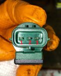
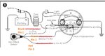
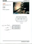
If you use the light pigtail on the hall effect sensor.
Black goes to #6&8 pins on the speedo
Green goes to the #3 pins on the speedo
Red goes to the #2 pin on the speedo
Red will be your 12V power from the speedo
Green will be your ground from the speedo
Black will be your signal to the speedo and is split across 2 pins.
Someone correct me if I have the signal and power reversed in that example. But, I believe that is correct.
")