Napalm00
Technical Excellence Contributor
Long story short I wanted to go to Disc on my Sals and keep the drum length axles and wide spaced hubs. I ended up creating an entire new braking system using a mix of Rover and GM parts due to cost and performance issues.
Lets start with the drum to disc. I wanted to stick with solid rotors all around for parts commonality and cheapness
****if you use these instructions you WILL NEED to replace the master cylinder as it wont have enough volume to operate the rear 4 piston calipers*****
I ordered or purchased:
FRC6139 (used from Adam's old axle) This is a wide spaced front disc hub for a 90/110 from 1983-2006
Solid Rotors front x4
RTC5572 x2 RH front solid rotor caliper
RTC5573 x2 LH front solid rotor caliper
Sfp000260 x2 Pads set for above calipers
Rtc5001 x2 retaining pin set for calipers
RTC3511G x2 Twin lip hub seals
FRC3988 x4 drive flange gaskets
Timken SET37 wheel bearings x4 from amazon
Stick of Lucas X-tra heavy duty green grease from walmart
and
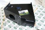
Red winches 4 piston caliper bracket for rear axles
Rear Axle Disc Brake Conversion - Landrover Defender
Russle speed bleeders 639630 m10x1x33
Russell 639630: Speed Bleeders 10mm x 1.0 | JEGS
****the red winches bracket is made for Rover stle rear axle but will work with modification for Sals (important later)****
Steps:
Install speed bleeders into all calipers
Remove rear wheels and place truck on axle stands
Remove drive flange bolts and axle circlip
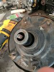
Remove drive flange and slide out axle
Remove drum retaning screw (may have to be drilled out)
Slack both adjusters on the backing plate with 13mm deep 6 point socket
Remove drum ( may need to be hammered off)
Loosen 11mm brake line fitting but leave in place on wheel cylinder
Bend back lock plate on the outer hub nut
Remove outer hub nut
remove lock plate
Remove inner hub nut
Yank entire hub assembly and put aside
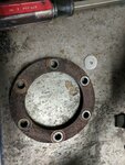
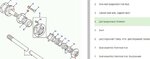
Remove the six 17mm head bolts and nuts around the center of the stub axle (nut on the outside face of the axle flange)
Now remove brake line from the wheel cylinder and cap it with a rubber plug to avoid a mess
Tap or yank off backing plate
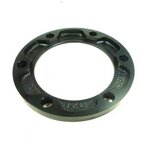
Keep the round bolt head spacer part # FRC3147
Put the fresh races and newly greased bearings into your FRC6139 front disc hubs and install the rear hub seal as deep as it will go, lips facing out
Install the new rotors onto the hubs with fresh lock washers or red locktite (or both)
Cleanup the stub axle with some red scotchbrite pad then brake or carb cleaner
Lightly grease the stub axle to aid assembly
Pack grease into the lips of the rear hub seal
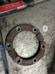
Cut FRC3147 (spacer we kept from the dum setup) into two pieces so you have two equal sizes spacers with three bolt holes each, stack these together.
We will use these spacers to mount the Red winches bracket
With three fresh long bolts and nuts from the Red winches hardware kit mount the bracket on the 2o'clock position on the axle
Use the thick and thin washers from the kit to align with the hub and rotor combo
Slide hub and rotor onto the stub axle (may need to wacked with a piece of wood or a deadblow as the new bearings are a tight fit)
Install one of the hubnuts enough to keep it in place
Install one of the calipers with the included hardware from the red winches hardware kit
Eyeball that the caliper is square to the rotor and centered over the rotor, if not remove or add washers to the red winches bracket and cut up spacers
(My truck only needed one thin washer on each bolt for the caliper to be dead center)
Now remove the hub, rotor, caliper
Install the rest of the bolts and tourque to spec adding loctite
Reinstall the hub, rotors, caliper, ect
Install hutnut, locking plate (replace if it is really jacked up) and outer hub nut
Install axle shaft
Install drive member and circlip
Sit back and relax you are 1/2way there !
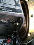
****TAKE NOTE on the short side of the axle you will need to notch the lower shock mount by 3/8 of an inch to allow the bracket and caliper to fit***
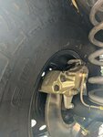
You have a decision to make now. you can leave the stock hardlines in place or replace them with flexlines and banjo bolts. I opted to move to flex lines as the hard lines are very close to the coils and the banjo will fit tighter and be more resistant to abrasion, AND it makes bleeding the nearly horizontal calipers much easier.
For my rear flex lines I used parts from pegasus racing:
1x 3-18-S-B 18in an3 flex line with swivel fitting one side and banjo on the other
1x 3-40-s-b 40in an3 flex line with swivel fitting one side and banjo on the other
4x 3241-3/8 soft copper 10mm or 3/8 crush washer
2x 3242-003 banjo bolt 10mmx1 short
2x 3265-16 male 10mmx1 convex to an3 male adapter
Frankly I measured the lines two times and the are still a little short so you can add 3-4in to the line lengths to give yourself more room.
The banjos will need to be shortened by about 5mm to avoid bottoming out in the caliper, i used a cutting disc to do this
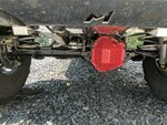
Put the metric to an adpaters in the "T" mounted on your axle diff cover
Install the shortened banjos with crush washers finger tight
Route flex line to the "T" and tourque
Now tourque the banjo bolts
OK 75% of the way there !
***From this point on im going to assume you know how to identify and create brake line nuts/flares/ect***
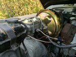
I wanted to reaplace the absolute garbage LR booster options and the garbage masters. After some research I found that a universal style 3 and 3/8 square pattern hot rod/chevy style brake booster will fit the Defender pedal box with minimal mods.
I settled on a 11in dual diaghpram brake booster as its was the largest I could find and that would fit my RHD truck, LHD may be different.
I also decided on a Corvette syle 1 1/8 in dual circut master. These are widely avialable but, make sure to get one rated for disc/disc applicaitons. Disc/Drumn versions will have a 10lb residual valve built into the rear circut that will cause the rear discs brakes to drag.
Booster
100% Brand New Universal 11 Dual Diaphragm Zinc Brake Booster Hot Rod Street | eBay
Master:
Tuff Stuff Performance #2071NB - TUFF STUFF Performance Accessories
You can also just buy a combo unit with a Dual 8in or dual 9in booster. All will fit and work, when i first built this i used a dual 8in to conserve space (that i didnt need to) and it worked 95% as well as the dual 11in
For example:
Tuff Stuff Performance #2124NB - TUFF STUFF Performance Accessories
I also added a wilwood 2lb residial valve to the rear circut only. I assumed that the nearly horizontal rear caliper mounting may cause issues with fluid runback. This wasnt the case but it cant hurt.
https://www.summitracing.com/parts/w...3783/overview/
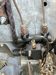
And to top it all off I used a SSBC single circut bias valve to control the flow of fluid to the rear brakes. Since the massive calipers have insane stopping power,if the truck is unloaded or not towing they can lockup to easily, this allows for adjustment of the rear circut bias(power).
Buy Universal Aluminum Adjustable Proportioning Valve for Rear Brake Bias at SSBC
The Steps for install:
Remove round covers from the side of the pedal box
Remove cotter pin from pedal arm pin
Push pin out and let fall to the floor of the truck
Collect up the pin, cotter and the heavy washers, put aside
Remove brake lines going into the stock master, note the position
remove 17mm nuts holding stock master to booster
remove stock master
remove 4 nuts holding stock booster to pedal box
remove vac hose from booster
remove booster
Measure the height of the pedal rod clevis ont the stock booster and note it
Using cutting disc cut off the clevis from the stock booster flush with the rear of the clevis
Discard stock booster
Place clevis in a vise and centerpunch the rear of the clevis
Drill with 21/64 or similar size
Tap clevis for 3/8-24 (fine thread)
INstall tapped clevis to aftermarket booster and check for height
Aftermarket booster rod will have to be trimmed aby about 5mm height to allow for pedal assembly and pin to line up
Remove clevis, mark and trim rod
INstall 3/8-24 jam nut then clevis with blue locktite
MEasure height then tourque into place
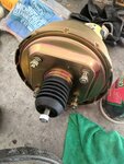
Aftermarket booster is now ready to mount
Looking that the defender pedal box you will see that the inner unused bolt holes are reeeeealy close to the bolt pattern of the aftermarket booster.
Using a unibit open up the holes and test fit the booster until good to go.
Install aftermarket booster onto defender pedalbox with opened up holes
Install pedal arm pin, washers and cotter pin after greasing them up.
Using a grease pencil or girlfriends nailpolish mark the end of the boosters actuator rod (part that pokes into the master)
Slide new master onto the booster then check that your booster and master are mating correctly, you should now have paint or grease on both the actuator rod and the master
If you do not have markings on both sides adjust the actuator as needed (some are threaded some need shims)
Create your required brake lines and fittings
I plumbed a 2lb resudial valve into the rear circut, this is optional
I also plubmed the SSBC brake bias valve ****AFTER**** the LR PWDA valve mounted on the bulkhead (see pics)
You plumb this after to avoid the PWDA from indicating a pressure issue on the rear circut.
IF you havent already rebuilt your PWDA now is a good time to (see my other post on this subject) or remove it, your choice
http://www.defendersource.com/forum/...ve-116281.html
Bench bleed your new master then install into the booster
If you have the old style coolant overflow tank it may need to be moved over an inch or so, or just temporarly removed to install the master.
Now hook up you new lines and bleed your brakes!
DONE !!!!!!
Phew that was alot to type. post or PM with questions
Lets start with the drum to disc. I wanted to stick with solid rotors all around for parts commonality and cheapness
****if you use these instructions you WILL NEED to replace the master cylinder as it wont have enough volume to operate the rear 4 piston calipers*****
I ordered or purchased:
FRC6139 (used from Adam's old axle) This is a wide spaced front disc hub for a 90/110 from 1983-2006
Solid Rotors front x4
RTC5572 x2 RH front solid rotor caliper
RTC5573 x2 LH front solid rotor caliper
Sfp000260 x2 Pads set for above calipers
Rtc5001 x2 retaining pin set for calipers
RTC3511G x2 Twin lip hub seals
FRC3988 x4 drive flange gaskets
Timken SET37 wheel bearings x4 from amazon
Stick of Lucas X-tra heavy duty green grease from walmart
and
Red winches 4 piston caliper bracket for rear axles
Rear Axle Disc Brake Conversion - Landrover Defender
Russle speed bleeders 639630 m10x1x33
Russell 639630: Speed Bleeders 10mm x 1.0 | JEGS
****the red winches bracket is made for Rover stle rear axle but will work with modification for Sals (important later)****
Steps:
Install speed bleeders into all calipers
Remove rear wheels and place truck on axle stands
Remove drive flange bolts and axle circlip
Remove drive flange and slide out axle
Remove drum retaning screw (may have to be drilled out)
Slack both adjusters on the backing plate with 13mm deep 6 point socket
Remove drum ( may need to be hammered off)
Loosen 11mm brake line fitting but leave in place on wheel cylinder
Bend back lock plate on the outer hub nut
Remove outer hub nut
remove lock plate
Remove inner hub nut
Yank entire hub assembly and put aside
Remove the six 17mm head bolts and nuts around the center of the stub axle (nut on the outside face of the axle flange)
Now remove brake line from the wheel cylinder and cap it with a rubber plug to avoid a mess
Tap or yank off backing plate
Keep the round bolt head spacer part # FRC3147
Put the fresh races and newly greased bearings into your FRC6139 front disc hubs and install the rear hub seal as deep as it will go, lips facing out
Install the new rotors onto the hubs with fresh lock washers or red locktite (or both)
Cleanup the stub axle with some red scotchbrite pad then brake or carb cleaner
Lightly grease the stub axle to aid assembly
Pack grease into the lips of the rear hub seal
Cut FRC3147 (spacer we kept from the dum setup) into two pieces so you have two equal sizes spacers with three bolt holes each, stack these together.
We will use these spacers to mount the Red winches bracket
With three fresh long bolts and nuts from the Red winches hardware kit mount the bracket on the 2o'clock position on the axle
Use the thick and thin washers from the kit to align with the hub and rotor combo
Slide hub and rotor onto the stub axle (may need to wacked with a piece of wood or a deadblow as the new bearings are a tight fit)
Install one of the hubnuts enough to keep it in place
Install one of the calipers with the included hardware from the red winches hardware kit
Eyeball that the caliper is square to the rotor and centered over the rotor, if not remove or add washers to the red winches bracket and cut up spacers
(My truck only needed one thin washer on each bolt for the caliper to be dead center)
Now remove the hub, rotor, caliper
Install the rest of the bolts and tourque to spec adding loctite
Reinstall the hub, rotors, caliper, ect
Install hutnut, locking plate (replace if it is really jacked up) and outer hub nut
Install axle shaft
Install drive member and circlip
Sit back and relax you are 1/2way there !
****TAKE NOTE on the short side of the axle you will need to notch the lower shock mount by 3/8 of an inch to allow the bracket and caliper to fit***
You have a decision to make now. you can leave the stock hardlines in place or replace them with flexlines and banjo bolts. I opted to move to flex lines as the hard lines are very close to the coils and the banjo will fit tighter and be more resistant to abrasion, AND it makes bleeding the nearly horizontal calipers much easier.
For my rear flex lines I used parts from pegasus racing:
1x 3-18-S-B 18in an3 flex line with swivel fitting one side and banjo on the other
1x 3-40-s-b 40in an3 flex line with swivel fitting one side and banjo on the other
4x 3241-3/8 soft copper 10mm or 3/8 crush washer
2x 3242-003 banjo bolt 10mmx1 short
2x 3265-16 male 10mmx1 convex to an3 male adapter
Frankly I measured the lines two times and the are still a little short so you can add 3-4in to the line lengths to give yourself more room.
The banjos will need to be shortened by about 5mm to avoid bottoming out in the caliper, i used a cutting disc to do this
Put the metric to an adpaters in the "T" mounted on your axle diff cover
Install the shortened banjos with crush washers finger tight
Route flex line to the "T" and tourque
Now tourque the banjo bolts
OK 75% of the way there !
***From this point on im going to assume you know how to identify and create brake line nuts/flares/ect***
I wanted to reaplace the absolute garbage LR booster options and the garbage masters. After some research I found that a universal style 3 and 3/8 square pattern hot rod/chevy style brake booster will fit the Defender pedal box with minimal mods.
I settled on a 11in dual diaghpram brake booster as its was the largest I could find and that would fit my RHD truck, LHD may be different.
I also decided on a Corvette syle 1 1/8 in dual circut master. These are widely avialable but, make sure to get one rated for disc/disc applicaitons. Disc/Drumn versions will have a 10lb residual valve built into the rear circut that will cause the rear discs brakes to drag.
Booster
100% Brand New Universal 11 Dual Diaphragm Zinc Brake Booster Hot Rod Street | eBay
Master:
Tuff Stuff Performance #2071NB - TUFF STUFF Performance Accessories
You can also just buy a combo unit with a Dual 8in or dual 9in booster. All will fit and work, when i first built this i used a dual 8in to conserve space (that i didnt need to) and it worked 95% as well as the dual 11in
For example:
Tuff Stuff Performance #2124NB - TUFF STUFF Performance Accessories
I also added a wilwood 2lb residial valve to the rear circut only. I assumed that the nearly horizontal rear caliper mounting may cause issues with fluid runback. This wasnt the case but it cant hurt.
https://www.summitracing.com/parts/w...3783/overview/
And to top it all off I used a SSBC single circut bias valve to control the flow of fluid to the rear brakes. Since the massive calipers have insane stopping power,if the truck is unloaded or not towing they can lockup to easily, this allows for adjustment of the rear circut bias(power).
Buy Universal Aluminum Adjustable Proportioning Valve for Rear Brake Bias at SSBC
The Steps for install:
Remove round covers from the side of the pedal box
Remove cotter pin from pedal arm pin
Push pin out and let fall to the floor of the truck
Collect up the pin, cotter and the heavy washers, put aside
Remove brake lines going into the stock master, note the position
remove 17mm nuts holding stock master to booster
remove stock master
remove 4 nuts holding stock booster to pedal box
remove vac hose from booster
remove booster
Measure the height of the pedal rod clevis ont the stock booster and note it
Using cutting disc cut off the clevis from the stock booster flush with the rear of the clevis
Discard stock booster
Place clevis in a vise and centerpunch the rear of the clevis
Drill with 21/64 or similar size
Tap clevis for 3/8-24 (fine thread)
INstall tapped clevis to aftermarket booster and check for height
Aftermarket booster rod will have to be trimmed aby about 5mm height to allow for pedal assembly and pin to line up
Remove clevis, mark and trim rod
INstall 3/8-24 jam nut then clevis with blue locktite
MEasure height then tourque into place
Aftermarket booster is now ready to mount
Looking that the defender pedal box you will see that the inner unused bolt holes are reeeeealy close to the bolt pattern of the aftermarket booster.
Using a unibit open up the holes and test fit the booster until good to go.
Install aftermarket booster onto defender pedalbox with opened up holes
Install pedal arm pin, washers and cotter pin after greasing them up.
Using a grease pencil or girlfriends nailpolish mark the end of the boosters actuator rod (part that pokes into the master)
Slide new master onto the booster then check that your booster and master are mating correctly, you should now have paint or grease on both the actuator rod and the master
If you do not have markings on both sides adjust the actuator as needed (some are threaded some need shims)
Create your required brake lines and fittings
I plumbed a 2lb resudial valve into the rear circut, this is optional
I also plubmed the SSBC brake bias valve ****AFTER**** the LR PWDA valve mounted on the bulkhead (see pics)
You plumb this after to avoid the PWDA from indicating a pressure issue on the rear circut.
IF you havent already rebuilt your PWDA now is a good time to (see my other post on this subject) or remove it, your choice
http://www.defendersource.com/forum/...ve-116281.html
Bench bleed your new master then install into the booster
If you have the old style coolant overflow tank it may need to be moved over an inch or so, or just temporarly removed to install the master.
Now hook up you new lines and bleed your brakes!
DONE !!!!!!
Phew that was alot to type. post or PM with questions
Attachments
-
 IMG_20170822_132244.jpg358.6 KB · Views: 406
 -
 IMG_20170822_132516.jpg375 KB · Views: 390
 -
 IMG_20170824_194840.jpg169 KB · Views: 394
 -
 IMG_20170906_151123.jpg615.4 KB · Views: 405
 -
 IMG_20170906_151133.jpg163.3 KB · Views: 450
 -
 IMG_20170906_151331.jpg424.1 KB · Views: 449
 -
 IMG_20170906_151343.jpg327.1 KB · Views: 538
 -
 IMG_20170906_151421.jpg249.4 KB · Views: 414
 -
 IMG_20170906_151431.jpg153.3 KB · Views: 388
 -
 061_11.jpg450.1 KB · Views: 477
 -
 frc3147.jpg17.7 KB · Views: 405
 -
 Untitled.jpg18.4 KB · Views: 364
