MountainD
Technical Excellence Contributor
On my 1991 (200TDI, 110), although I have a low fuel warning light, it has never worked. Since I replaced the rear chassis harness, I noticed that the connector plug is a 5-pin connector (connects the rear harness to the short harness to the tank). This 5 pin connector has 3 pins, 2 blanks. The 3 pins correspond to a signal wire for the level, a low fuel warning wire and a reference ground--this connects to the side mounted fuel return/sender. Although each side of the harness has 3 wires, the contactors only align for the reference ground and fuel level, but the white/slate wire doesn't align. So I fixed that and modified a new pin and crimped it on and melted it into the new connector.
Now the issue. I know where the white/slate wire ends up in the engine bay from the rear harness. I also see a white/slate wire going into the main harness bundle at the binnacle tracing it from the warning light cluster. But for the life of me, I can't find where this terminates so I can hook up this circuit. Any help located that? I do see a white/purple wire at an engine bay harness plug but my cursory continuity check doesn't show that to be the right one at the warn light...
Here they show it not hooked up to anything....

Connect those dots and I will have a low fuel warning light")
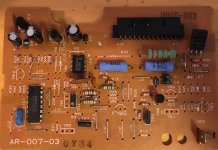
I think if I can figure that part out, I may do an small circuitry unit for "anti-slosh" warning signal so it doesn't blink in corners. And, frankly, it may have that mysterious circuit that is embedded into the harness that some folks can find that basically does that---and if that is the case, the white/purple wire may be correct in the engine bay and the module is burnt out creating the short from my resistance test to the cluster...
Otherwise I do have one of the low fuel circuit adjustable things that I can always hook up.... (bought this last year: https://www.ebay.com/itm/251309976772 )
Now the issue. I know where the white/slate wire ends up in the engine bay from the rear harness. I also see a white/slate wire going into the main harness bundle at the binnacle tracing it from the warning light cluster. But for the life of me, I can't find where this terminates so I can hook up this circuit. Any help located that? I do see a white/purple wire at an engine bay harness plug but my cursory continuity check doesn't show that to be the right one at the warn light...
Here they show it not hooked up to anything....
Connect those dots and I will have a low fuel warning light
I think if I can figure that part out, I may do an small circuitry unit for "anti-slosh" warning signal so it doesn't blink in corners. And, frankly, it may have that mysterious circuit that is embedded into the harness that some folks can find that basically does that---and if that is the case, the white/purple wire may be correct in the engine bay and the module is burnt out creating the short from my resistance test to the cluster...
Otherwise I do have one of the low fuel circuit adjustable things that I can always hook up.... (bought this last year: https://www.ebay.com/itm/251309976772 )
Last edited: